DRYIT Semi-Continuous Tray Drier
Practical Action
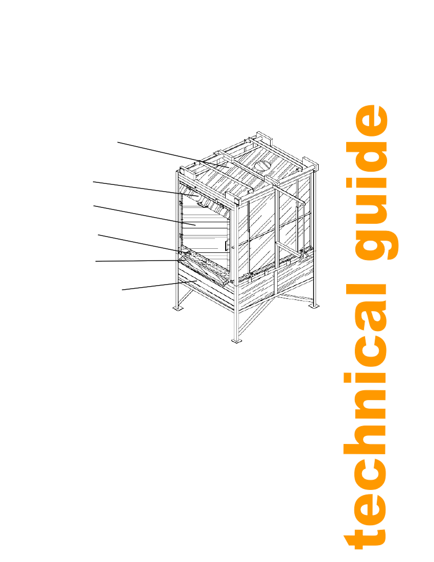
The trays, cladding and doors are shown in the position on the completed drier in figure 2.
Drying cabinet
cladding
Door
Door
Trays
Door
Base cladding
Figure 2: Cladding trays and doors
Construction Of Tray Drier
This section describes each major component together with a possible construction
procedure.
Base Frame
See drawing TD001
The base is made from mild steel angle, steel bar and steel plate. It consists of two
rectangles, 1110 x 1420 mm with four legs welded on the outside at the corners, bracing,
feet and two tray supports.
Mild steel angle is usually manufactured with a radius on the inside corner. Therefore, for the
legs to fit closely to the rectangles' outside corners, the corners must not be sharp. A way to
avoid sharp corners is to use 'snub' ends, as shown in figure 4.
7